Home

ghiaccio ombra ristrutturazione gps schematic diagram Scrivi Riparazione possibile Alla meditazione

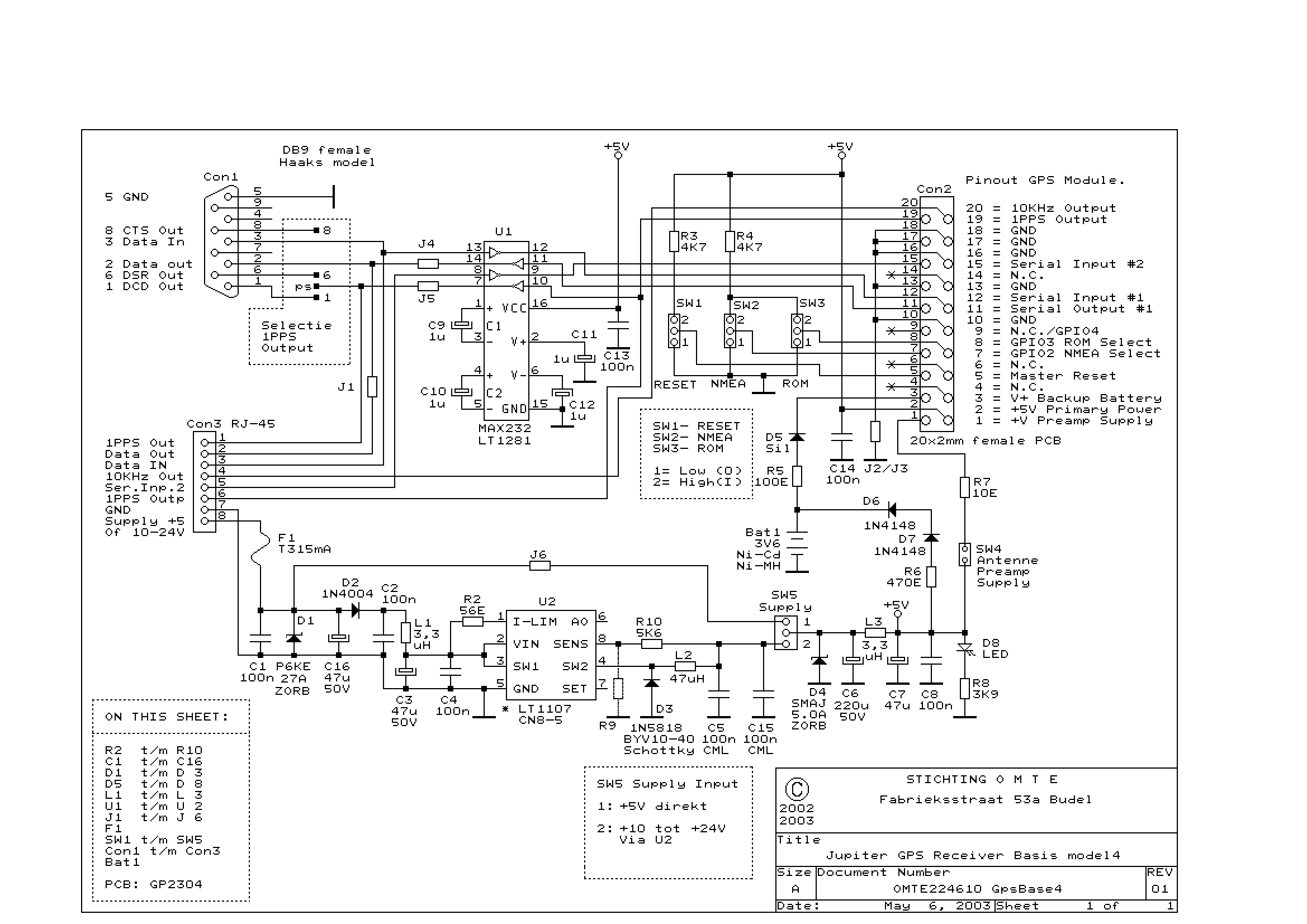
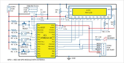
Simple and Low-Cost GPS Clock | Full Electronics Project

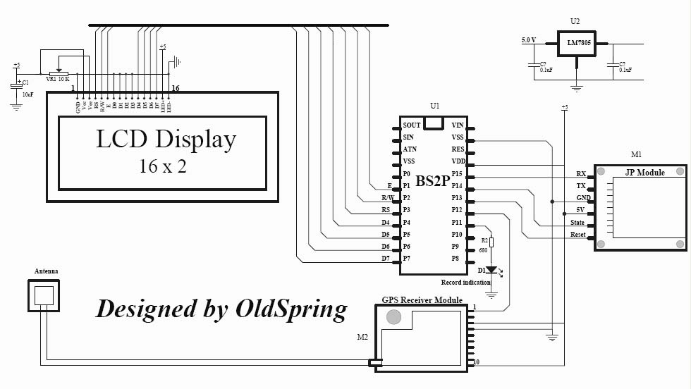
gps tracker project gps module jp module lcd dispaly under  Repository-circuits -41104- : Next.gr
gps tracker project gps module jp module lcd dispaly under Repository-circuits -41104- : Next.gr

Circuit Design (GPS) Part 1

NEO-6M GPS Module Interfacing with ESP8266 NodeMCU | Lindevs

Diagram description GPS support kit

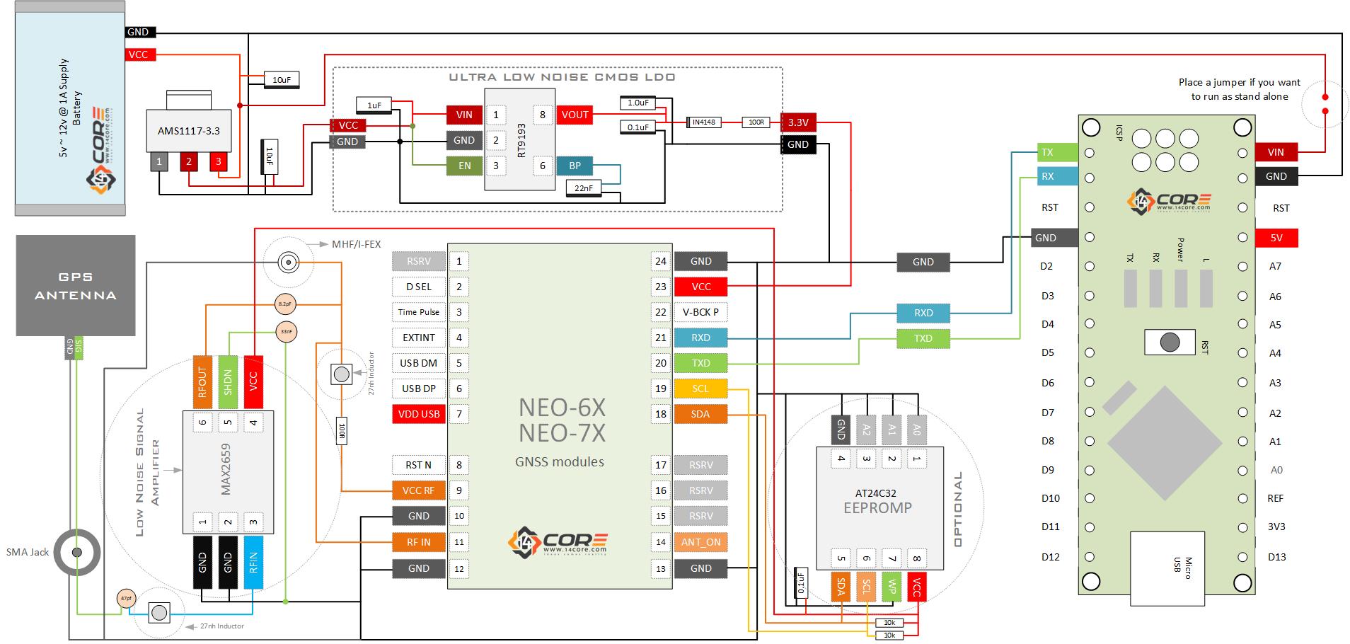
Neo-6-Neo7-GNSS-GPS-Module-Schematics-Wiring-Guide-14core | 14core.com

NEO-6M GPS Module — An Introduction

Interfacing PIC microcontroller with GPS module | mikroC Projects

Arduino based Vehicle Tracker using GPS and GSM | Arduino, Vehicle tracking  system, Arduino gps
Arduino based Vehicle Tracker using GPS and GSM | Arduino, Vehicle tracking system, Arduino gps

GPS sensor
GPS sensor

Circuit diagram of GPS- and GSM-based vehicle tracking system | Vehicle  tracking system, Vehicle tracking, Tracking system
Circuit diagram of GPS- and GSM-based vehicle tracking system | Vehicle tracking system, Vehicle tracking, Tracking system

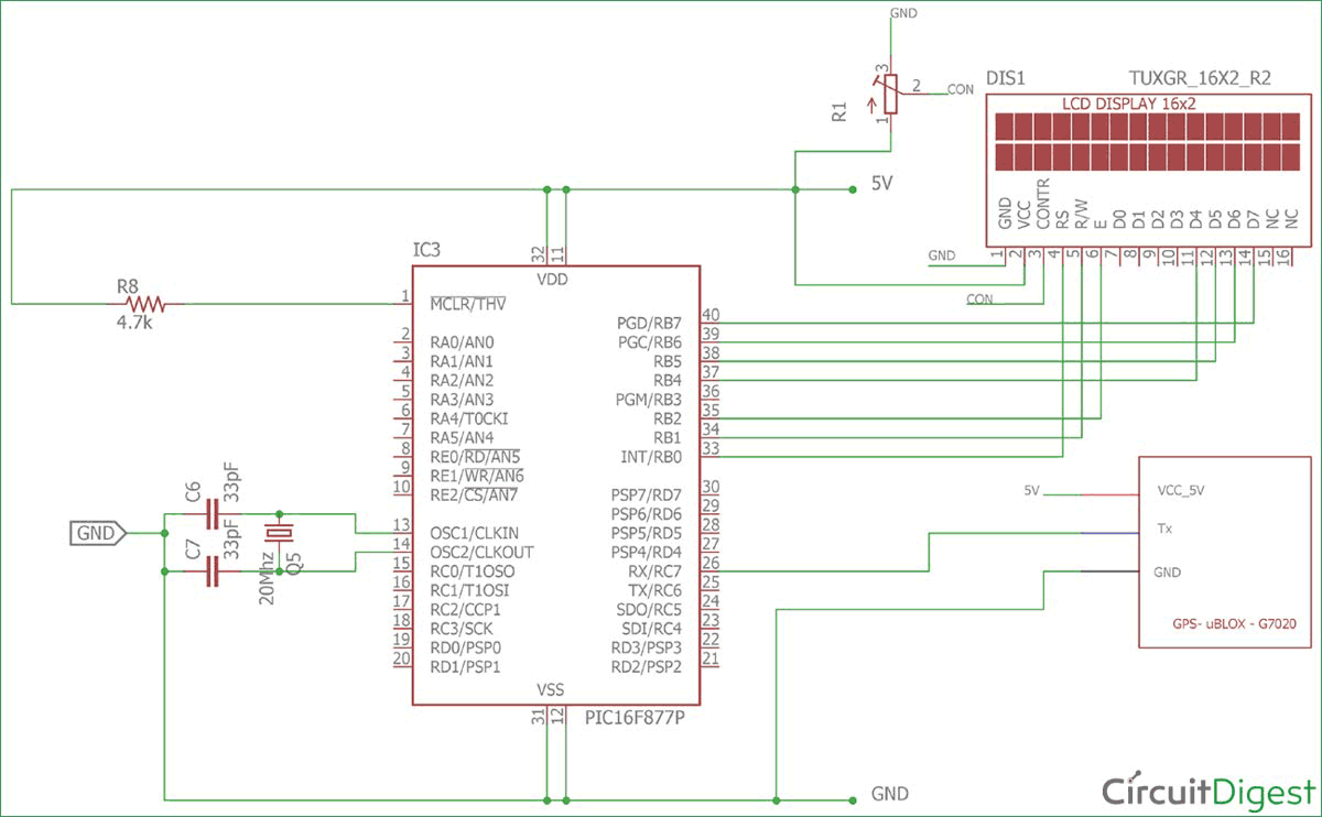
Interfacing GPS Module with PIC Microcontroller

GPS Clock using Arduino

PCB: GPS and GSM Based Vehicle Tracking System : 3 Steps - Instructables

Circuit Diagram and Program to Interface a GPS Receiver with AT89S51 | Free  Microcontroller Projects - 8051-AVR-PIC
Circuit Diagram and Program to Interface a GPS Receiver with AT89S51 | Free Microcontroller Projects - 8051-AVR-PIC

Standalone GPS Receiver with LCD Display | Electrical projects, Arduino, Circuit  diagram
Standalone GPS Receiver with LCD Display | Electrical projects, Arduino, Circuit diagram

GPS/DGPS DISPLAY J-NAV 500 - Schematic Diagram | JRC(Japan Radio Co., Ltd.)

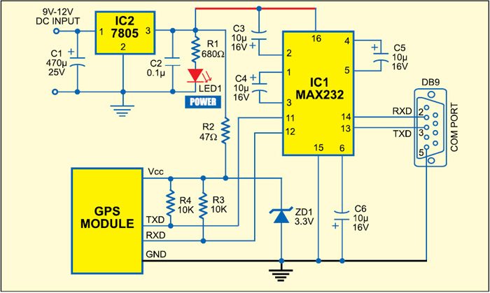
PC-Based GPS Receiver | Full Electronics DIY Project

Electronic circuit schematic: (a) sensor and GPS board, and (b) thrust... |  Download Scientific Diagram
Electronic circuit schematic: (a) sensor and GPS board, and (b) thrust... | Download Scientific Diagram

2: Simple schematic diagram to understand the Differential-GPS. | Download  Scientific Diagram
2: Simple schematic diagram to understand the Differential-GPS. | Download Scientific Diagram

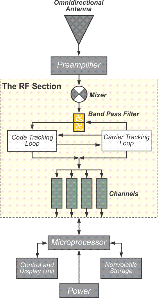
Lesson 4: Receivers and Methods

Schematic Diagram of the GPS, GSM/GPRS Module and the Microcontroller. |  Download Scientific Diagram
Schematic Diagram of the GPS, GSM/GPRS Module and the Microcontroller. | Download Scientific Diagram
GPS/GSM Module. Circuit Diagram – magictaleblog

MAX2769 GPS Reference Design - Reference Schematic - Maxim

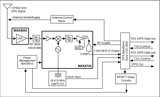
Complete Stand-Alone GPS Receiver Solution with MAX2742

GPS Module Circuit Diagram | Download Scientific Diagram